¶ Thermal Bridging in DEAP
¶ What is a Thermal Bridge?
Ideally, in order to minimise heat loss a dwelling would be completely enclosed in a continuous layer of insulation. In reality, there will be areas of the building fabric where it is impossible to maintain the continuity of insulation, particularly around doors and windows, and at the junctions between the building elements, e.g. the junction between the ground floor and the walls of the dwelling.
A thermal bridge occurs where there is a gap in insulation or a reduced level of insulation in the building fabric. This has a lower thermal resistance, which means it allows heat to escape more easily from the dwelling.
Figure 6.23 shows an example of a thermal bridge at the junction of a concrete slab ground floor with a masonry cavity wall. Because of the need to ensure structural stability, it is not possible to maintain a continuous layer of insulation across the junction.
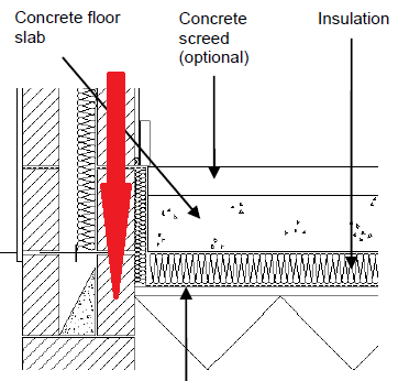
There is a gap between the floor insulation (under the slab) and the wall insulation (in the cavity). Heat will flow through this gap at a higher rate than through the floor or wall, both of which are well-insulated.
This is the thermal bridge.
Measures can be taken to reduce the effect of the thermal bridge, e.g.
- The use of edge insulation around the perimeter of the floor;
- Bringing the wall insulation down below the top of the floor;
- The use of blocks of low thermal conductivity in the lower course(s) of the inner leaf of the cavity wall.
Section 1.3.3 of the TGD L requires that particular care must be taken to prevent excessive heat loss at these thermal bridges. Failure to do so could lead to problems with condensation and mould growth.
The rest of this section sets out,
- How thermal bridging is accounted for in DEAP: the thermal bridging factor;
- The use of the Acceptable Construction Details and certified details to determine the thermal bridging factor;
- The documentary evidence required to support the use of a thermal bridging factor;
- An example of a non-default thermal bridging factor calculation, with examples of the supporting documentation required;
- The responsibilities of the BER Assessor in respect of the thermal bridging factor.

Heat Loss due to Thermal Bridges
In DEAP the heat loss through each building element - floor, wall, roof, window, door – depends on the area and the thermal transmittance (U-value) of that building element. However, while this accounts for the heat loss through those building elements, it does not account for heat loss at the junctions between those elements.
For example, in Figure 6.24, the wall area & wall U-value, and the roof area & roof U-value, account for the heat loss through the green sections. However, the heat loss through the junction of wall and roof, marked by the red dashed line, must also be accounted for.
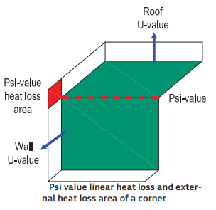
This is described as a linear thermal bridge as the heat loss occurs along the line of the junction between wall and roof. In the same way that the rate of heat loss through a unit area of a building element is measured by its thermal transmittance (U-value), the rate of heat loss through a unit length of a linear thermal bridge is measured by its linear thermal transmittance. It is represented by the Greek letter Psi (Ψ) and so it is also known as the Psi-value. It is measured in units of W/mK.
In general, the Psi-value represents the additional heat flow through the linear thermal bridge over and above that through the adjoining plane elements. The Psi-value is calculated using numerical modelling in accordance with BR497 and BS EN ISO 10211:2017 and is dependent on a number of factors including:
- The geometry of the junction and DEAP measurement conventions.
- The level of insulation at the junction.
The transmission heat loss coefficient associated with non-repeating thermal bridges is defined as:
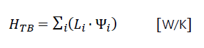
Where Li is the length of each junction and Ψ is the linear thermal transmittance of that junction.
The transmission heat loss coefficient is calculated in DEAP as:
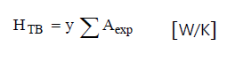
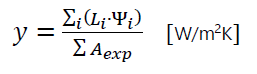
Where Aexp is the total area of exposed elements, and the “y value”, or thermal bridging factor, is defined as:
Acceptable Construction Details (ACDs)
In order to provide guidance on minimising heat loss through the thermal bridges in a dwelling, a set of junction details have been published for the most common construction methods used in Ireland. These are known as the Acceptable Construction Details (ACDs). For each junction in the ACDs the following is provided:
- A drawing of the junction detail;
- Construction requirements to achieve the necessary thermal performance;
- Requirements to ensure continuity of the air barrier;
- Options for the type of air barrier;
- The Psi-value of the junction detail – (also given in Tables D1 to D6 of TGD L).
These details are available to download from the Department of Housing, Planning and Local Government website.
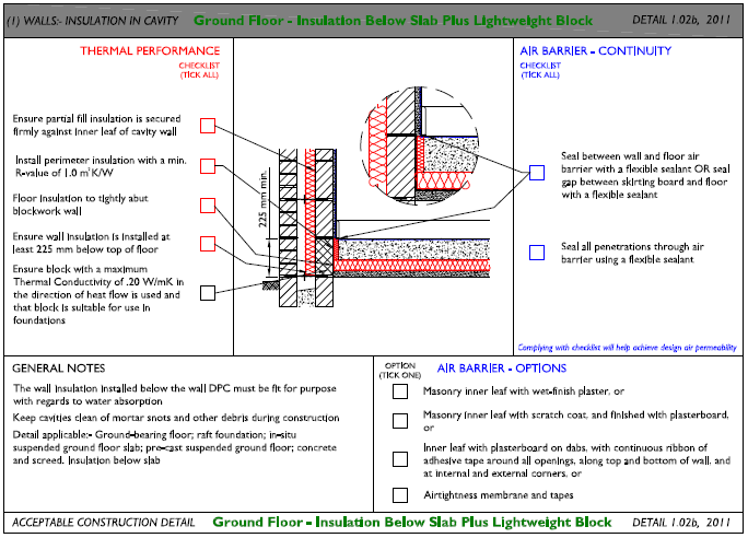
Figure 6.25 has an example of an ACD: Detail 1.02b for the junction of a Cavity Wall – Insulation in Cavity and a Ground Floor – Insulation below Slab plus Lightweight Block. Note the requirements that must be met, for example, “Install perimeter insulation with a min. R-value of 1.0 m2K/W” and “Ensure wall insulation is installed at least 225 mm below top of floor”.
For the purposes of the BER, if an ACD is being used, only the Thermal Performance checklist needs to be completed.
¶ Junction Details not in the ACDs
The ACDs cover many common construction junction types, but they are not exhaustive. For example, the following features are typically not represented in the ACDs: cantilevered sections, non-standard window positions, façade bracketry (e.g. helping hand brackets).
As we will see in Section 6.5.5, where a non-default thermal bridging factor is to be used in DEAP, any key junctions not covered by ACDs need to be thermally modelled to determine the junction Psi-value. The Psi-value for non-ACD junctions can be taken from any of the following sources:
- A numerical model of the specific junction carried out and certified by an NSAI registered thermal modeller or equivalent. Details of the NSAI Thermal Modellers Scheme can be found here. Many construction material manufacturers have developed their own library of certified details.
- NSAI Agrément certificates or equivalent – this approach is typically used for building systems rather than individual junction details.
- The BRE Certified Thermal Products Database, which can be found here.
This is a database of Psi-values which have been independently assessed and certified by BRE.
BRE are a UKAS Accredited Certification Body. The calculated Psi-values provided by the BRE Certified Thermal Products Database are acceptable for use in DEAP and NEAP.
Please note: specifiers and constructors of these details should ensure that thermally approved details for the UK comply with all Parts of the Irish Building Regulations including Parts A-Structure, B-Fire, C-Site Preparation and Resistance to moisture, and D-Materials and Workmanship.
¶ Accounting for heat loss at junctions in DEAP
In DEAP, the additional heat loss due to thermal bridging is accounted for by the Thermal Bridging Factor, also called the y-value, expressed in W/m2K. DEAP multiplies this number by the total exposed surface area of the dwelling to give the heat loss due to thermal bridging from all key junctions in the dwelling. This section sets out the appropriate value to enter for the y-value, which depends on how thermal bridging has been addressed in the dwelling.
Note: The following types of junctions are considered key junctions where they include a heat loss plane element:
- Floor to wall (includes party walls)
- Wall to wall (corners & party walls)
- Roof to wall (includes party walls)
- Lintel above window/door
- Sill below window
- Window/door jamb
This list is not exhaustive. Any junction in the dwelling which has a relatively long length or a high rate of heat loss, or both, should be considered a key junction.
¶ No information on junction details
Where no information is provided to the BER Assessor about the junction details, the default thermal bridging factor should be used: y-value = 0.15 W/m2K.
Even where this value is used, there is a responsibility to ensure junction design meets the TGD L requirements in relation to limiting risk of surface condensation, as set out in Appendix D of the TGD L. This falls outside of BER assessments and is not considered here.
¶ Thermal Bridging in accordance with Building Regulations 2005 TGD L applies.
y = 0.11 W/m2K: This only applies to new dwellings where Building Regulations 2005 TGD L apply.
This value may be used when sign-off by the relevant person (as defined in the previous section) indicates that all details in the dwelling have been constructed in accordance with both:
I. Diagrams 3 and 4, and Sections 1.2.4 and 1.2.5 of Building Regulations 2005 TGD L;
II. The details set out in the Homebond publication “Right on site, issue no. 28” or the fifth or later editions of the Homebond manual.
¶ All key junctions covered by ACDs
Where all of the key junctions in a dwelling are covered by details taken from the ACDs, there are two options for the thermal bridging factor:
Option 1: Use the thermal bridging factor, y-value = 0.08 W/m2K.
The use of this value is allowed for new dwellings only, where the dwelling has been designed and constructed in accordance with the acceptable construction details.
This could be shown in one of the following ways:
- Signed confirmation by the Design Certifier that the dwelling is designed in accordance with the ACDs and by the Assigned Certifier that the dwelling was constructed in accordance with the design;
OR,
- If a “Declaration of Intention to Opt Out of Statutory Certification” is provided to the BER Assessor, a signed confirmation by the building owner or by the builder appointed in the “Notice of Assignment of Builder”, that the dwelling is designed in accordance with the ACDs and that the dwelling was constructed in accordance with the design;
OR,
- Where the signed confirmation at points (a) or (b) is not available, documentary evidence is required to support the use of a y-value of 0.08 W/m2K in a BER assessment.
The purpose of the supporting evidence is to show that:
- All junctions in the dwelling have been considered;
- All key junctions have been identified;
- Each key junction has been designed and built in accordance with the associated ACD.
For example, these requirements would be met by the following documentation:
- Construction Drawings showing all junctions in the dwelling.
- A schedule of junctions. This would,
- List all junctions in the dwelling.
- Identify all key junctions;
- Reference the associated ACD for each key junction.
- A copy of the ACD for every key junction.
These documents should reference the dwelling being assessed and should be signed by the relevant person, i.e. one of,
- Developer,
- Builder,
- Architect,
- Engineer,
- Assigned certifier,
confirming that the key junctions identified were designed and built in accordance with the associated ACDs. (For New-Provisional ratings it is sufficient to confirm design only, as the dwelling has not yet been built.)
Option 2: Use a non-default thermal bridging factor.
Documentary evidence is required to support a non-default y-value.
The purpose of the supporting evidence is to show that:
- All junctions in the dwelling have been considered;
- All key junctions have been identified;
- Each key junction has been designed and built in accordance with the associated ACD;
- The non-default y-value has been calculated correctly.
For example, these requirements would be met by the following documentation:
- Construction Drawings showing all junctions in the dwelling.
- A schedule of junctions. This would,
- List all junctions in the dwelling.
- Identify all key junctions;
- Reference the associated ACD for each key junction.
- A copy of the ACD for every key junction, as listed in the junction schedule.
- The calculation of the non-default y-value.
The calculation of the y-value requires the length of each key junction in the dwelling so this should be clearly set-out either in the drawings or the schedule.
These documents should reference the dwelling being assessed and should be signed by the relevant person, i.e. one of,
- Developer,
- Builder,
- Architect,
- Engineer,
- Assigned certifier,
confirming that the key junctions identified were designed and built in accordance with the associated ACDs. (For New-Provisional ratings it is sufficient to confirm design only, as the dwelling has not yet been built.)
The use of a calculated y-value is typically of benefit to projects. For the majority of dwellings, the calculated y-value will be below the default 0.08 W/m2K value for standard house types. This directly affects the overall energy performance of the dwelling.
Apartments will commonly have calculated y-values significantly above the 0.08 W/m2K value. This is not necessarily due to poor detailing of junctions but is mainly due to the DEAP measurement convention. For the purpose of design-stage assessments, it is recommended to use the 0.15 W/m2K default value for apartments. This allows a margin for error in the event that a y-value of 0.08 W/m2K is not achieved in the final construction.
SEAI have developed a Thermal Bridging Calculator which can be used to carry out y-value calculations. The instructions for using the thermal bridging calculator can be found here.
¶ All junctions covered by a combination of ACDs and certified details
In this case a non-default y-value must be calculated. The Thermal Bridging Calculator which can be used in this case.
Documentary evidence is required to support a non-default y-value. The purpose of the supporting evidence is to show that:
- All junctions in the dwelling have been considered;
- All key junctions have been identified;
- Each key junction has been designed and built in accordance with the associated ACD/certified detail;
- The non-default y-value has been calculated correctly.
For example, these requirements would be met by the following documentation:
- Construction Drawings showing all junctions in the dwelling.
- A schedule of junctions. This would,
- List all junctions in the dwelling.
- Identify all key junctions;
- Reference the associated ACD/certified detail for each key junction.
- A copy of the associated ACD/certified detail for every key junction, as listed in the junction schedule.
- The calculation of the non-default y-value.
- The calculation of the y-value requires the length of each key junction in the dwelling so this should be clearly set-out either in the drawings or the schedule.
These documents should reference the dwelling being assessed and should be signed by the relevant person, i.e. one of,
- Developer,
- Builder,
- Architect,
- Engineer,
- Assigned certifier,
confirming that the key junctions identified were designed and built in accordance with the associated ACD/certified detail. (For New-Provisional ratings it is sufficient to confirm design only, as the dwelling has not yet been built.)
¶ Example – All key junctions covered by a combination of ACDs and certified details
The dwelling in the following example is a 2-storey semi-detached house.
The details of the building fabric are set out in the following table:
| Element | Description | Calculated U-value |
| Wall Type 1 | Cavity walls with partial fill insulated cavity | 0.14 |
| Ground Floor | Solid concrete floor with insulation below slab | 0.14 |
| Roof Type 1 | Pitched roof, insulated at ceiling level | 0.13 |
| Roof Type 2 | Flat roof | 0.14 |
| First Floor | Timber intermediate floor | - |
| Party Wall** | Solid masonry | - |
| Wall Type 2** | Solid masonry internal partition penetrating ground floor slab | - |
| Wall Type 3** | Timber stud partition | - |
| ** While the heat loss through this plane element is typically not accounted for in DEAP, if this non-heat loss plane element adjoins another heat loss element, heat loss at the junction may need to be accounted for. | ||
Documentary evidence for BERs
In this example, the following evidence has been provided to substantiate a non-default y-value.
(a) Drawings with all junctions identified
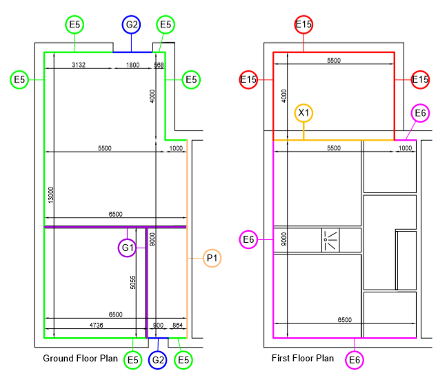
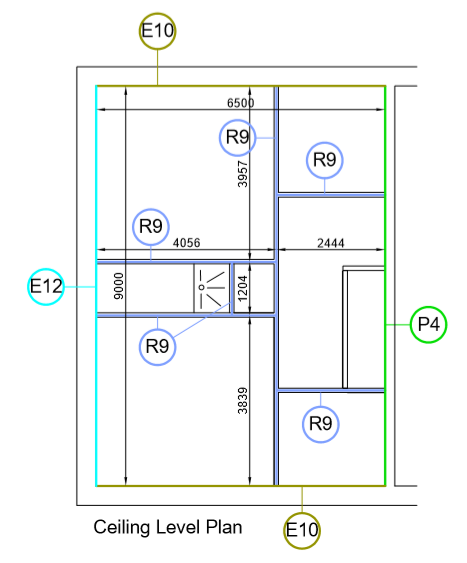
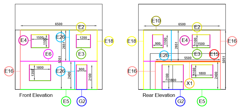
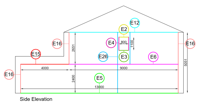
Figure 6.26 and 6.27 provide an example of a set of plans and elevations with all the junctions identified and labelled. These drawings are usually prepared by the designer of the dwelling. The drawings should reference the dwelling being assessed. While this level of detail may not be available from the designer of the dwelling, at a minimum all key junctions must be identified.
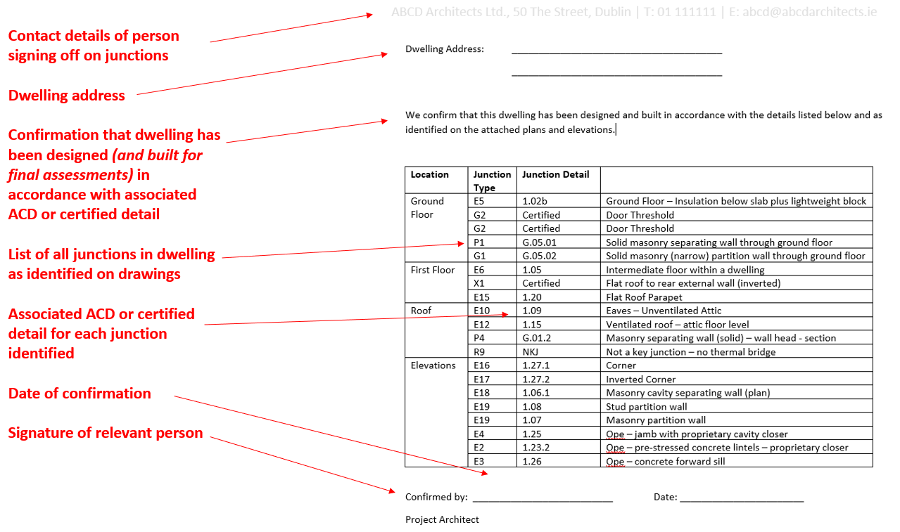
(b) Schedule of all junctions identified in the drawings
In this example, a schedule of all junctions in the dwelling has been provided.
This schedule should contain the following information:
- A clear reference to the dwelling being assessed.
- A list of all of the junctions in the dwelling.
All junctions must be included in this list. The relevant person (Section 6.5.5) may consider a particular junction not to be a key junction, e.g. a door threshold, but must still include this junction here and explicitly state that it is not a key junction.
- For each junction that is considered to be a key junction, the associated ACD or certified detail must be identified. Note that all of the junction types listed in Section 6.5.5 are considered to be key junctions.
The schedule should be signed by the relevant person (developer/builder/architect/engineer/assigned certifier) confirming the junctions identified were designed and built in accordance with the associated ACDs and/or certified details.
Figure 6.28 is an example of a schedule of junctions for a dwelling.
(c) Copy of all ACDs / Certified Details
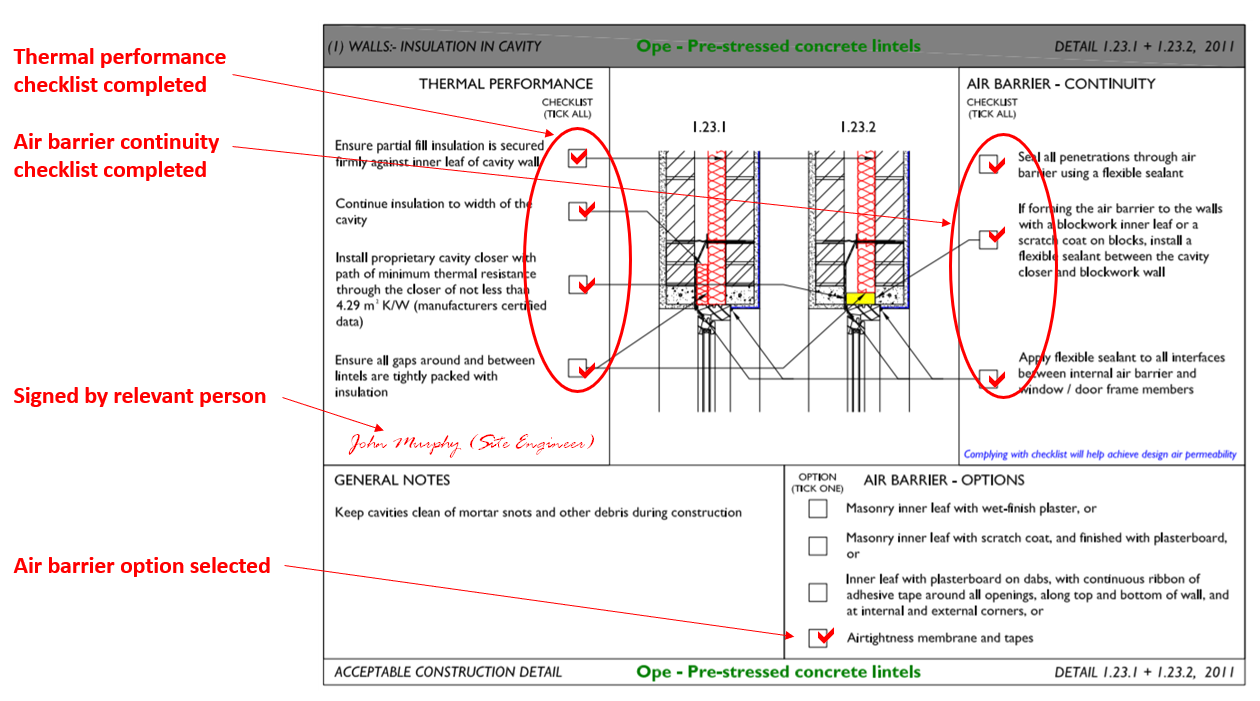
A copy of all ACDs and/or certified details referenced in the junction schedule should be provided. Each detail should be signed by the relevant person confirming the junction was designed and built (or designed for provisional ratings) in accordance with the relevant detail.
Where a Ψ-value is used which is calculated by a certified thermal modeller, the junction detail clearly referencing the certified psi-value and thermal modeller name and registration details must be provided to the BER assessor
Where reports supporting the certified Ψ-value are not available in accordance with these requirements, this Ψ-value may not be used, and the y-value reverts to a default 0.15W/m2K.
Figure 6.29 is an example of an ACD that has been appropriately completed and signed-off.
Note that,
- The checklist for Thermal Performance has been completed.
- It has been signed by the relevant person.
- The checklists for “Air Barrier – Continuity” and “Air Barrier – Options” have been completed in this example but these do not need to be completed in order to support the y-value.
(d) Copy of non-default y-value calculation.
The basic form of the calculation is as follows:
For each key junction in the dwelling:
- Measure the length of the junction, L;
- Identify the Ψ-value for the junction, either from the ACD documentation or from a thermal modelling report;
- Calculate the heat loss coefficient for the junction = Ψ x L.
The Total Thermal Bridging Heat Loss Coefficient (HTB) is the sum of the heat loss coefficients for all key junctions.
Finally, the Thermal Bridging Factor, y = Total Thermal Bridging Heat Loss Coefficient/Total Exposed Area.
This is the value that is entered into DEAP.
Ψ-values for each junction detail in the ACDs are provided in Tables D1 - D6 of Appendix D of the TGD L.
Figure 6.30 shows an excerpt from Table D1 with the data for Detail 1.02b highlighted.
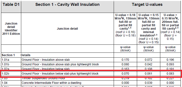
The highlighted section shows three Ψ-values which can be used for this junction, depending on the U-values of the elements involved and the location of the insulation. Table 14 shows this in more detail:
Table 2.39 - Psi values for an ACD
|
Wall Insulation Type |
Target Wall U-value (W/m2K) |
Allowed Wall U-values (W/m2K) |
Target Floor U-value (W/m2K) |
Allowed Floor U-values (W/m2K) |
Psi-value |
| Cavity insulation | 0.18 | 0.18 | 0.18 | 0.16 – 0.21 | 0.070 |
| Cavity insulation and internal insulation | 0.15 | 0.12 – 0.17 | 0.15 | 0.12 – 0.18 | 0.061 |
| Cavity insulation | 0.15 | 0.12 – 0.17 | 0.15 | 0.12 – 0.18 | 0.083 |
1) If the wall U-value or the floor U-value are not within one of the Allowed U-value ranges specified above (in Column 3 and Column 5 of Table 2), then an ACD Ψ-value cannot be used. In such a case, there are three possible ways to proceed:
- The junction would have to be thermally modelled to get the correct Ψ-value, which would allow the calculation of a non-default y-value; or,
- If all key junctions were covered by ACDs, then y = 0.08 W/m2K could be used; or,
- Otherwise, the default thermal bridging factor, y = 0.15 W/m2K would have to be used.
2) An additional restriction is imposed in cases where the U-value of one flanking element is above its target U-value and the U-value of the other flanking element is below its target U-value, as follows:
Where two building elements have one U-value above its target while the other is below its target U-value, the aggregate percentage change from the respective target U-values in the table should not exceed 20% for the Ψ-value to be valid.
Taking the example of the wall-floor detail 1.02b again: let’s take a case where the wall has a partially filled cavity giving a U-value of 0.16 W/m2K. The target U-value for this wall is 0.15 W/m2K, so the wall U-value is 6.67% above the target. Therefore, the floor U-value can’t be more than 13.33% below the target floor U-value for this Ψ-value to be valid, i.e. if the floor U-value is below 0.13 W/m2K then the Ψ-value cannot be used.
Note that this restriction does not apply where both U-values are above their respective target U-values (but within the allowed ranges). Also, this restriction does not apply where both U-values are below their respective target U-values (but within the allowed ranges).
Table 16 has the details of the y-value calculation for this example dwelling.
Table 2.40 - Calculation of a y-factor
| Location | Type | Junction Detail | Ψ (W/mK) | L (m) | Ψ*l (W/K) | |
| Ground Floor | E5 | 1.02b | Ground Floor - Insulation below slab plus lightweight block | 0.083 | 27.30 | 2.266 |
| G2 | Certified | Door Threshold | 0.054 | 1.80 | 0.098 | |
| G2 | Certified | Door Threshold | 0.069 | 0.90 | 0.062 | |
| P1 | G.05.1 | Solid masonry separating wall through ground floor | 0.120 | 9.00 | 1.080 | |
| G1 | G.05.2 | Solid masonry (narrow) partition wall through ground floor | 0.150 | 11.56 | 1.733 | |
| First Floor | E6 | 1.05 | Intermediate floor within a dwelling | -0.001 | 16.50 | -0.017 |
| X1 | Certified | Flat roof to rear external wall (inverted) | -0.063 | 5.50 | -0.348 | |
| E15 | 1.2 | Flat Roof Parapet | 0.206 | 13.50 | 2.781 | |
| Roof | E10 | 1.09 | Eaves - Unventilated Attic | 0.053 | 13.00 | 0.689 |
| E12 | 1.15 | Ventilated Roof - Attic floor level | 0.210 | 9.00 | 1.890 | |
| P4 | G.01.2 | Masonry separating wall (solid) - wall head - section | 0.229 | 9.00 | 2.061 | |
| R9 | NKJ | Not a key junction | 0.000 | 23.20 | 0.000 | |
| Elevations | E16 | 1.27.1 | Corner | 0.035 | 12.50 | 0.438 |
| E17 | 1.27.2 | Inverted Corner | -0.055 | 2.40 | -0.132 | |
| E18 | 1.06.1 | Masonry Cavity Separating Wall (plan) | 0.032 | 10.10 | 0.323 | |
| E19 | 1.08 | Stud Partition Wall | 0.000 | 10.60 | 0.000 | |
| E19 | 1.07 | Masonry Partition Wall | 0.000 | 4.80 | 0.000 | |
| E4 | 1.25 | Ope - Jamb with proprietary cavity closer | 0.006 | 24.30 | 0.146 | |
| E2 | 1.23.2 | Ope - Pre-stressed concrete lintels- proprietary closer | 0.006 | 12.20 | 0.073 | |
| E3 | 1.26 | Ope - concrete forward sill | 0.019 | 9.50 | 0.181 | |
| Transmission Heat Loss Coefficient, Htb (W/K) | 13.324 | |||||
| Total Exposed Surface Area, Σ Aexp (m2) | 291.322 | |||||
| y-value (W/m2K) | 0.046 | |||||
The SEAI Thermal Bridging Calculator can also be used to calculate a y-value.