¶ Non-default U values: Pitched roof U-value calculations
Extensive detail on U-value calculations is provided in EN6946, Appendix A of TGD L and BR443. BR443 Section 8 (U-values for roofs) has a useful summary of the methods to be applied. The more common pitched roof scenarios are detailed below.

Example 1: Pitched roof, insulated at ceiling, ventilated attic
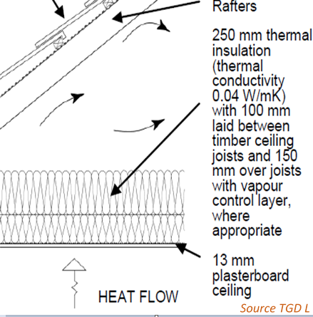
Insulation is first laid between the joists to completely fill the space between the joists. Another (continuous) layer of insulation is then laid over the joists. The joists act as a repeating thermal bridge through the first layer of insulation. Heat flows through the timber joists more easily than it flows through the insulation. In numerical terms, timber has a higher thermal conductivity than the insulation. A thermal bridge increases the rate of heat loss but in this case, it is an unavoidable consequence of the roof structure. The second layer of insulation is laid over the joists, so does not have thermal bridges.
To calculate the U-value of this type of roof – or any structure with one or more thermally-bridged layers - it is necessary to account for the different heat-paths through the structure. This is done using the Upper and Lower Resistance Method as described in detail in Example A3 of TGD L. In this method the upper and lower thermal resistances of the structure are calculated and averaged to obtain the U-value of the roof.
The following notes are relevant to this calculation:
- The internal and external surface thermal resistances are shown in Section 4.1 of BRE 443 and EN6946.
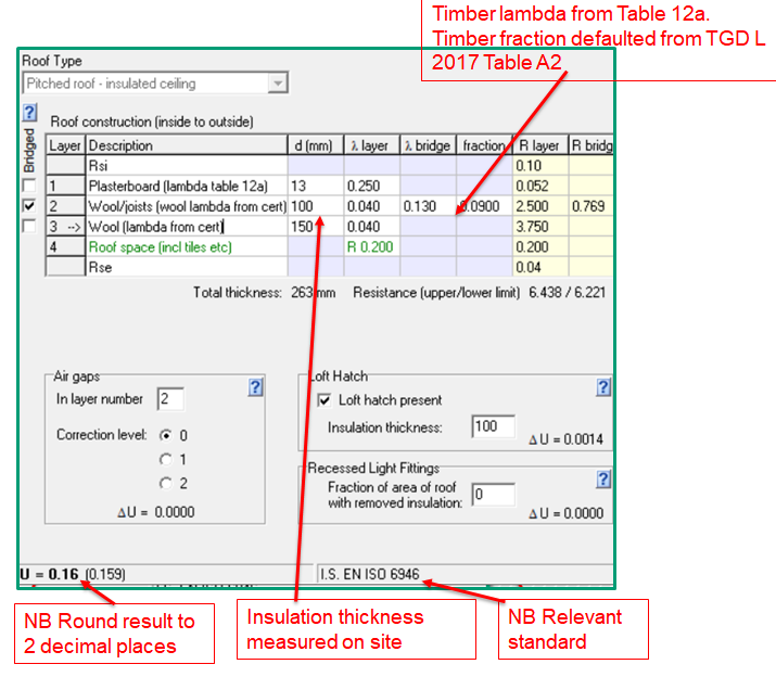
- The ventilated roof space thermal resistance, 0.20m2K/W, is taken from TGD L and is based on EN6946.
- The thermal conductivity values of construction materials can be taken from Table 12a of the DEAP manual where certified data isn’t available. For insulation materials, the values in Table 12b can be used for Existing and New-Provisional BER Assessments when certified data is not available. For New-Final BER Assessments, accredited test data must be used for insulation materials.
- The fractional area of thermal bridging can be calculated if the size and frequency of the timber joists are known. Otherwise default values from Table A2 of TGD L can be used. The default value for a flat ceiling, i.e. timber joists, and insulation between the joists, is 9 % thermal bridging which is equivalent to a fractional area of 0.09.
- Sections 4.9 and 8 of BRE 443 discuss minor corrections due to air gaps and outlines when those corrections are required.
The U-value calculated by this method (U = 0.16 W/m2K) is entered in DEAP along with the corresponding heat loss area, namely the area of the flat ceiling. The U-value calculation (using the BRE U-value calculator in this case) is shown below.
As an aside, the U-value of a flat roof structure with thermal bridging – insulation between timber joists – is calculated with the same method though without accounting for the ventilated roof space of the pitched roof.

Example 2: Pitched roof, insulated at rafter level, unventilated attic space with a flat ceiling
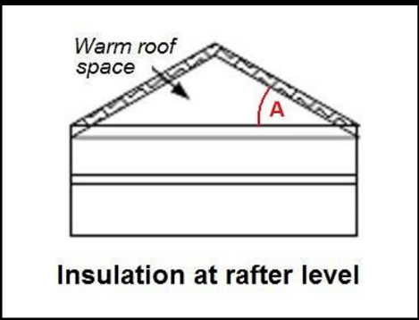
This example shows the calculation of the U-value of a pitched roof when the insulation is installed at rafter level. The attic is not accessible by a fixed staircase so is not included in the Total Floor Area in DEAP. In this example, adapted from Appendix B of TGD L, the roof has 120 mm rafters with 120 mm phenolic foam insulation between the rafters and 50 mm of the same insulation below the rafters as shown in the close-up of the sloping section. The pitch of the roof is 30°. This is the angle ‘A’ in the diagram below.
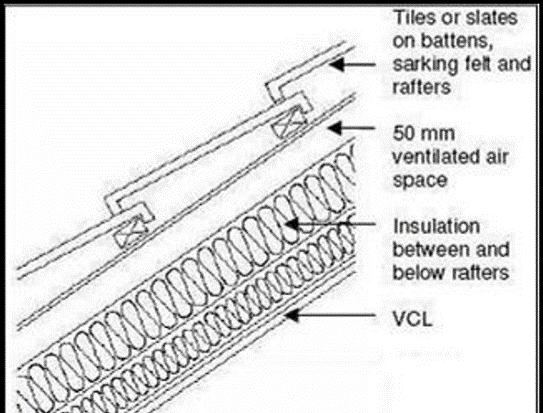
The structure is like the previous example, with several uniform layers and a thermally-bridged layer so the Upper and Lower Resistance method is used. The Thermal Resistances are tabulated below:
| Layer | Thickness (m) | Thermal Conductivity (W/mK) | Thermal Resistance (m2K/W) | Corrected Thermal Resistance (m2K/W) |
|---|---|---|---|---|
| External Surface* | - | - | 0.04 | 0.035 |
| Insulation (between rafters) * | 0.12 | 0.025 | 4.8 | 4.157 |
| Timber Rafters* | 0.12 | 0.13 | 0.92 | 0.799 |
| Sloping Insulation (below rafters) * | 0.05 | 0.025 | 2 | 1.732 |
| Roof Space | - | - | 0.16 | 0.16 |
| Plasterboard | 0.0125 | 0.25 | 0.05 | 0.05 |
| Internal Surface | - | - | 0.10 | 0.10 |
Although the form of the calculation is the same as the previous calculation there are crucial differences:
- Even though the insulation is located on the slope of the roof, the area of the flat ceiling is used for heat loss calculations in DEAP;
- The thermal resistance of each layer in the sloped section of the roof must be multiplied by the cosine of the pitch of the roof as detailed in BRE 443 Section 8 (Insulation at rafter level – flat ceiling). In the table above these layers are marked with an asterisk (*). In this example, the thermal resistance of these layers is multiplied by the Cos (30°) = 0.866 to give the Corrected Thermal Resistance in the last column of the table;
- Following guidance in BRE 443 the thermal resistance of the roof void between slope and ceiling is taken as 0.16 m2K/W;
- The default percentage of thermal bridging is taken from Table A2 of TGD and has a value of 8%.
- The remainder of the calculation follows the method of upper and lower resistances to derive the total U-value.

Example 3: Pitched roof, insulated at rafter level, habitable attic space accessible by fixed staircase
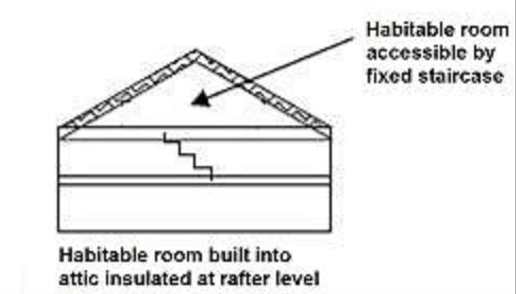
This differs from Example 2, as the attic space is included in the assessment floor area. In this case the heat loss area to be entered in DEAP is the area of the sloping roof and the U-value calculation is for the sloping section. In this example, a roof structure like Example 2 above is used, namely, 120 mm rafters with 120 mm phenolic foam insulation between the rafters and 50 mm of phenolic foam insulation below the rafters. There is a plasterboard finish. The slope is a thermally bridged structure, so the U-value is calculated with the Upper and Lower Resistance method.
| Layer | Thickness (m) | Thermal Conductivity (W/mK) | Thermal Resistance (m2K/W) |
|---|---|---|---|
| External Surface | - | - | 0.04 |
| Insulation (between rafters) | 0.12 | 0.025 | 4.8 |
| Timber Rafters | 0.12 | 0.13 | 0.92 |
| Sloping Insulation (below rafters) | 0.05 | 0.025 | 2 |
| Plasterboard | 0.0125 | 0.25 | 0.05 |
| Internal Surface | - | - | 0.10 |
The remainder of the calculation follows the method of the previous example with the Upper Resistance = 6.36 m2K/W and Lower Resistance = 5.78 m2K/W leading to a U-value of 0.16 W/m2K. The U-value is entered in DEAP along with the area of the sloping roof. There is no Cosine multiplier applied to the thermal resistances as the sloping area is the heat loss area in DEAP.
As before, the default percentage of thermal bridging is taken from Table A2 of TGD L and has a value for a sloped ceiling of 8%. BRE 443 section 4.8 provides further detail on accounting for ventilated air gaps where present in the sloping roof structure.

Example 4: Room-in-roof, insulation follows the shape of the room
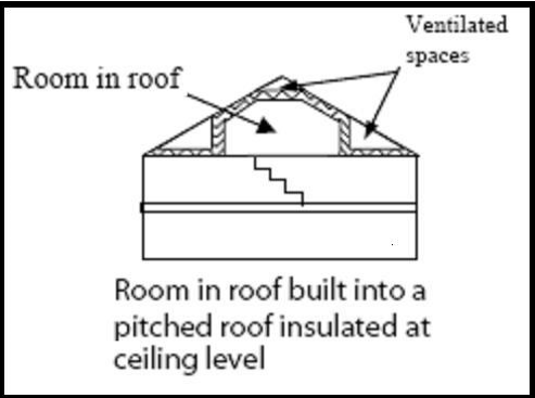
There are two ways to calculate heat loss for a room-in-roof construction such as that shown in the diagram.
(i) Room-in-roof approximation
For Existing Dwellings, DEAP gives the option to automatically calculate the total exposed area and default U-value of the room-in-roof’s heat loss surfaces. The area approximates the total area of the heat loss roof and wall sections of the room-in-roof as described in Appendix S of the DEAP manual and Section 0 above. The Assessor must account for the heat loss area of the ceiling of the storey below separately (ceiling below exposed to the ventilated1 crawl-spaces).
(ii) Manual calculation
In cases where the Assessor can identify the levels of insulation on the room-in-roof and there are varying levels of insulation (or in new dwellings), the Assessor must manually calculate the heat loss for each section of the room-in-roof. The area approximation referenced above is not used in this case.
- Flat Ceiling Section of Room-in-roof: U-value calculated as per a standard pitched roof insulated at ceiling level as per Example 1 above and entered in DEAP along with the area of flat ceiling.
- Sloped Ceiling Section of Room-in-roof: U-value calculated as per a standard sloped ceiling, as described in Example 2 above and entered in DEAP along with the area of sloped ceiling.
- Knee Wall Section of Room-in-roof: U-value calculated as per a standard wall (e.g. use the Upper and Lower Resistance method for an insulated timber stud knee-wall). A thermal resistance of Ru = 0.5 is added to the knee-wall U-value as shown in Diagram A5 of TGD L. The U-value and the area of the knee walls are entered in DEAP (walls section).
- Semi-exposed Ceiling of Room Below: U-value calculated as per a standard roof (Upper and Lower Resistance method). A thermal resistance of Ru = 0.5 is added to the ceiling U-value as shown in Diagram A5 of TGD L 2011. The U-value and the area of the semi-exposed ceiling are entered in DEAP.