¶ Solar Water Heating
A solar water collector coupled with solar water storage reduces the fuel needed for DHW. The solar water storage can heat the lower part of a multi heat source cylinder or as a separate solar cylinder. Solar water heating cannot provide all the hot water or space heating requirements and a main water and space heating fuel type must be specified at all times.
The DEAP software displays a figure for ’Solar fraction‘ indicating the proportion of the solar hot water yield relative to the total dwelling hot water demand. If this figure is greater than 60% for a solar water heating system, it is likely that the system is oversized, and the system design may need to be reconsidered. In the case of solar space and water heating systems, solar fraction may well exceed 60%.
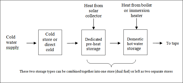
The working principle of solar hot water systems is shown in Figure H1. Examples of arrangements are given in figure H2. These do not show all possible arrangements and the procedures in this appendix are applicable to any arrangements that follow the same principles.
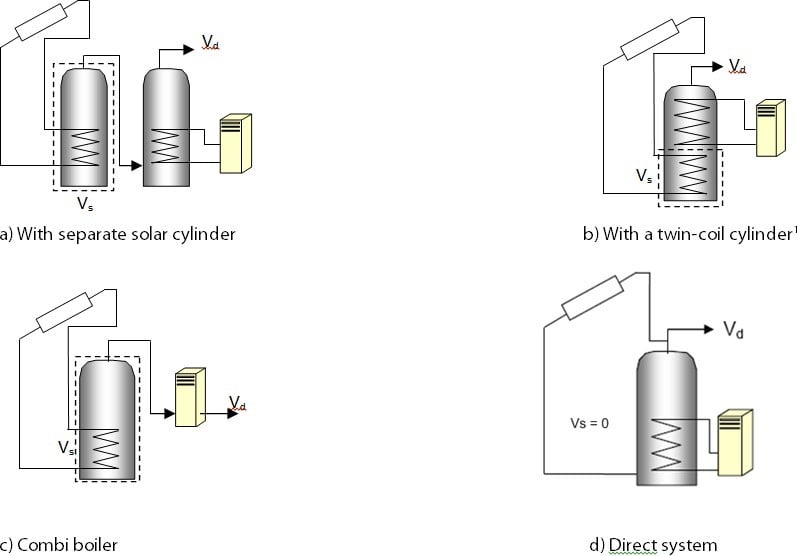
Vs (indicated by the dashed line) is the dedicated solar storage volume. See text below concerning the effective solar volume. Vd is the daily hot water demand.
Water from the cold supply is either fed (directly or via a cold feed cistern) to the preheat zone where it is heated by solar energy. Then the water passes to the domestic hot storage (separate hot water cylinder or upper part of combined cylinder) which is heated to the required temperature by a boiler or an electric immersion.
There are three main types of solar collector:
- Unglazed: the overall performance of unglazed collectors is limited by high thermal losses;
- Glazed flat plate: a flat plate absorber (which often has a selective coating) is fixed in a frame between a single or double layer of glass and an insulation panel at the back;
- Evacuated tube: an absorber with a selective coating is enclosed in a sealed glass vacuum tube.
The performance of a solar collector is represented by its zero-loss efficiency (proportion of incident solar radiation absorbed in the absence of thermal loss) and its heat loss coefficient (heat loss from collector to the environment per unit area and unit temperature difference).
For existing Dwellings, if solar collectors are present, the following data can be used for any unavailable parameters:
- Total aperture area of all collectors = 3 m²
- ŋ0 and/or a1 from Table H1
- Facing south, pitch 30°, modest overshading
- Combined cylinder, dedicated solar part one-third of total, or if a combi boiler the cylinder identified is a dedicated solar cylinder.
- Pump is not solar powered.
¶ Solar calculations
The solar contribution to domestic hot water for each month is given by:
Qs.m = Sm x Zpanel x Aap x η0 x UFm x f(a1/η0) x f(Veff/Vd) (H1)
Where:
- Qs,m = solar input for month m, kWh
- Sm = monthly solar radiation incident on the collector plane, kWh/m²
- Zpanel = overshading factor for the solar panel
- Aap = aperture area of collector, m²
- ŋ0 = zero-loss collector efficiency (or optical efficiency)
- UFm = utilisation factor for month m
- a1 = linear (first order) heat loss coefficient of collector, W/m²K
- f(a1/ŋ0) = collector performance factor = (see below)
- Veff = effective solar volume, litres
- Vd = daily hot water demand, litres
- f(Veff/Vd) = solar storage volume factor = 1.0 + 0.2 ln(Veff/Vd)
The annual solar input is the sum of the monthly values: Qs = Σ Qs,m
¶ Monthly incident solar radiation
Monthly horizontal solar radiation Hm (kWh/m²) is obtained from the meteorological data for the location. The solar radiation incident on the tilted collector surface Sm is calculated by applying a transposition factor Tm to the horizontal radiation:
Sm = Hm × Tm. (H2)
The transposition factor varies by month and depends on the collector's orientation and tilt, the site latitude, and the monthly solar declination. Three intermediate coefficients A, B, and C are first derived from the collector tilt β (degrees from horizontal) using orientation-dependent constants k1 to k9 given in Table H2:
A = k1 × sin(β/2)³ + k2 × sin(β/2)² + k3 × sin(β/2)B = k4 × sin(β/2)³ + k5 × sin(β/2)² + k6 × sin(β/2)C = k7 × sin(β/2)³ + k8 × sin(β/2)² + k9 × sin(β/2) + 1
The transposition factor for each month is then:
Tm = A × cos(φ − δm)² + B × cos(φ − δm) + C (H3)
where φ is the site latitude (degrees) and δm is the solar declination for month m (degrees).

Utilisation factor
The utilisation factor accounts for the proportion of available solar energy that can usefully contribute to the hot water demand. For each month, the solar-to-load ratio Rm is calculated as:
Rm = (Sm × Zpanel × Aap × η0) / Qdhw,m (H4)
where Qdhw,m is the monthly domestic hot water heating requirement (kWh).
The monthly utilisation factor is then:
UFm = 1 − exp(−1/Rm) (H5)
Where the cylinder is heated indirectly by a boiler or other heat generator and does not have a cylinder thermostat, UFm is reduced by a factor of 0.9.

Collector performance factor
The collector performance factor f(a1/η0) accounts for the reduction in output due to thermal losses and is given by:
f(a1/η0) = 0.87 − 0.034 × (a1/η0) + 0.0006 × (a1/η0)² if a1/η0 < 20 (H6)
f(a1/η0) = 0.604 − 0.0087 × (a1/η0) if a1/η0 ≥ 20 (H6)
The collector’s gross area is the projected area of complete collector (excluding any integral means of mounting and pipework). The aperture area is the opening that admits solar radiation.
Solar panel performance can be taken from one of the following sources:
a) The HARP database;
b) Triple E register;
c) Certified data for the collector concerned according to:
- IS EN 12975-2, Thermal solar systems and components – Solar collectors – Part 2: Test methods
OR - IS EN 9806:2017 Solar Energy – Solar Thermal Collectors – Test Methods. The aperture area, and the performance characteristics 0 and a1 related to aperture area, are obtained from the test certificate;
d) Table H5.1.
The effective solar volume is:
- in the case of a separate pre-heat tank (such as arrangements (a) or (c) in figure H2), the volume of the pre-heat tank;
- in the case of a combined cylinder (such as arrangement (b) in figure H2), the volume of the dedicated solar storage plus 0.3 times the volume of the remainder of the cylinder. Source: CIBSE Solar heating design and installation guide;
- in the case of a thermal store (hot-water-only or integrated as defined in Appendix B) where the solar coil is within the thermal store, the volume of the dedicated thermal storage;
- in the case of a direct system (such as arrangement (d) in Figure H2), 0.3 times the volume of the cylinder. Arrangement (d) is entered as a combined cylinder in DEAP with no dedicated solar storage.
DEAP requires the dedicated solar storage value which may be calculated by the following means:
- Derived from indication of heating coil locations on a cylinder datasheet. The datasheet may contain a diagram of the cylinder showing the location of the internal cylinder coils or location of upper and lower coil connections to the cylinder. The dedicated solar storage applies to the volume of storage below the coil lying directly above the solar heated coil. If for example, the combined cylinder is 300L and the connections of the upper coil are halfway down the cylinder side, then the dedicated solar storage can be assumed to be 150L.
- It may also be possible to determine the location of the coil connections on site. The dedicated solar storage is the cylinder volume lying below the coil directly above the solar coil.
- The cylinder documentation/datasheet may state the volume dedicated to solar storage along with relevant standards for storage volume specification. This is acceptable, but assessors should cross-check that the stated dedicated solar storage volume does not include sections of the cylinder heated by coils above the solar heated coil.
- Where the dedicated solar volume is not known, then, the dedicated solar volume can be assumed to be one third of the total cylinder volume.
Note: The overall performance of solar water systems depends on how the hot water system is used, such as daily draw-off patterns and the use of other water heating devices such as a boiler or an immersion. The procedure described here is not suitable for detailed design in a particular case. It is intended to give a representative value of the solar contribution to domestic water heating over a range of users.
¶ Calculation steps for solar water heating
Table 5.7 - Part 1 — Quantities determined once
| Step | Quantity | Calculation | Reference |
|---|---|---|---|
| 1 | Aperture area of collector, Aap [m²] | From test certificate. If only gross area is known, multiply by ratio in Table 5.1 | Table 5.8 |
| 2 | Zero-loss collector efficiency η0 | From test certificate or default | Table 5.8 |
| 3 | Collector heat loss coefficient, a1 [W/m²K] | From test certificate or default | Table 5.8 |
| 4 | Collector performance ratio, a1/η0 [W/m²K] | = a1 ÷ η0 | |
| 5 | Collector performance factor, f(a1/η0) | From equation H6 | Eq. H6 |
| 6 | Overshading factor, Zpanel | From overshading description | Table 5.11 |
| 7 | Dedicated solar storage volume, Vs [litres] | See guidance above | |
| 8 | Total cylinder volume [litres] | Required if combined cylinder | |
| 9 | Effective solar volume, Veff [litres] | If separate pre-heat tank: Veff = Vs; if combined cylinder: Veff = Vs + 0.3 × (Vtotal − Vs) | |
| 10 | Daily hot water demand, Vd [litres] | From water heating calculation | |
| 11 | Volume ratio, Veff/Vd | = Veff ÷ Vd | |
| 12 | Solar storage volume factor, f(Veff/Vd) | = 1.0 + 0.2 × ln(Veff/Vd) | Eq. H1 |
Table 5.8 - Part 2 — Quantities calculated for each month
| Step | Quantity | Calculation | Reference |
|---|---|---|---|
| 13 | Horizontal solar radiation, Hm [kWh/m²] | From meteorological data | |
| 14 | Solar declination, δm [°] | From meteorological data | |
| 15 | Transposition factor, Tm | From orientation, tilt, latitude and δm | Eq. H3, Table 5.2 |
| 16 | Incident solar radiation, Sm [kWh/m²] | = Hm × Tm | Eq. H2 |
| 17 | Solar energy available [kWh] | = Sm × Zpanel × Aap × η0 | |
| 18 | Monthly DHW requirement, Qdhw,m [kWh] | From water heating calculation | |
| 19 | Solar-to-load ratio, Rm | = solar energy available ÷ Qdhw,m | Eq. H4 |
| 20 | Utilisation factor, UFm | = 1 − exp(−1/Rm) | Eq. H5 |
| 21 | Adjusted utilisation factor | If no cylinder thermostat: UFm × 0.9; otherwise UFm | |
| 22 | Monthly solar input, Qs,m [kWh] | = solar energy available × adjusted UFm × f(a1/η0) × f(Veff/Vd) | Eq. H1 |
Annual total: Qs = Σ Qs,m (sum of monthly values)
¶ Table 5.9 - Default collector parameters
| Collector type | η0 | a1 (W/m2K) | Ratio of aperture area to gross area |
|---|---|---|---|
| Evacuated tube |
0.6 |
3 |
0.72 |
| Flat plate, glazed |
0.75 |
6 |
0.90 |
| Unglazed |
0.9 |
20 |
1.00 |
¶ Table 5.10 - Constants for calculating the solar radiation transposition factor
| Constant | South | SE/SW | East/West | NE/NW | North |
|---|---|---|---|---|---|
| k1 | -0.66 | -2.95 | 1.44 | 0.165 | 26.3 |
| k2 | -0.106 | 2.89 | -2.36 | -3.68 | -38.5 |
| k3 | 2.93 | 1.17 | 1.07 | 3 | 14.8 |
| k4 | 3.63 | 5.67 | -0.514 | 6.38 | -16.5 |
| k5 | -0.374 | -3.54 | 1.89 | -4.53 | 27.3 |
| k6 | -7.4 | -4.28 | -1.64 | -0.405 | -11.9 |
| k7 | -2.71 | -2.72 | -0.542 | -4.38 | -1.06 |
| k8 | -0.991 | -0.25 | -0.757 | 4.89 | 0.0872 |
| k9 | 4.59 | 3.07 | 0.604 | -1.99 | -0.191 |
¶ Table 5.11 - Overshading factor
| Overshading | % of sky blocked by obstacles | Overshading factor |
|---|---|---|
| Heavy | > 80% | 0.5 |
| Significant | > 60% - 80% | 0.65 |
| Modest | 20% - 60% | 0.8 |
| None or very little | < 20% | 1.0 |
|
Notes: Overshading must be assessed separately for solar panels, taking account of the tilt of the collector. Usually there is less overshading of a solar collector compared to overshading of windows for solar gain. |
||
¶ Group solar DHW
Where solar panels are used in a group heating system, the total collector area and the total dedicated solar store volume should be divided between the dwellings in proportion to the total floor area of the dwellings (these can be rounded to the nearest 0.01 m² and 1 litre).
Example:
A block of 24 flats, eight with floor area of 50 m² and 16 with floor area of 60 m². Total aperture area of solar panels is 40 m² and the total solar storage volume is 1000 litres. The small flats are each assigned 1.47 m² and 37 litres, and the larger flats 1.76 m² and 44 litres. The assessor should keep a record of the relevant group heating system details used in carrying out this calculation (total floor area, number of dwellings, etc.).
The calculation is described in Table H.1 for single systems, with the above parameters and the orientation, pitch and overshading of the panels set at values representative of the whole installation. Usually, the solar store is separate, and the arrangement is equivalent to that of diagram a) in Table H.2.
The solar storage in this case is not entered as a heat loss cylinder as ’Storage losses on the ‘Water Heating: options and storage’ tab. The ‘Storage losses’ entry is only for cylinders heated by heat sources other than solar heating.
A separate procedure for solar space and water heating is detailed in Appendix Q.
¶ Multiple solar collectors of different orientation
The Annual Solar Radiation falling on a solar collector is taken from Table 5.2 of the DEAP manual. The values in this table must not be interpolated; instead, the nearest value in the table must be used: e.g. for a solar collector on a roof facing south with a pitch of 25° use the nearest value in the table which is for a south-facing roof with a pitch of 30°, i.e. a value of 1074 kWh/m2.
The DEAP software assumes that all the solar collectors on a dwelling have the same orientation, but this is not always the case. In this situation the correct value for the annual solar radiation must be calculated by an area-weighted average.
For example, consider a dwelling with:
- 2m2 of collectors on a south-facing roof with a tilt of 30°, and,
- 1m2 of collectors on an east-facing roof with a tilt of 60°.
According to DEAP Table 5.2 the collectors on the south-facing roof receive 1074 kWh/m2 and the collectors on the east-facing roof receive 778 kWh/m2.

This value is entered for the “Annual Solar Radiation” in DEAP, and the “Aperture Area of Solar Collector” is equal to the total area of the collectors which is 3m2 in this case.
Table 5.12 - Evidence Requirements for solar hot water
| Water heating: solar | ||
|---|---|---|
|
Guidance on re-use of data for Water heating: solar can be found here |
||
| Data Entry Item | Guidance | Documentary Evidence |
| Solar thermal panels |
Photographic evidence of existence and layout of solar panels must be taken to support the data inputs. Installation and manual documentation or product labelling should be sought. If available, a copy of relevant documentation must be taken. Determine make and model where possible. Solar panels on the dwelling may be listed on the HARP database or certified data may be obtainable. |
|
| Aperture area of solar panels. |
|
|
| Zero loss collector efficiency | ||
| Collector heat loss coefficient | ||
| Annual solar radiation | Tilt and orientation need to be established and entered into the Solar PV section of the Onsite Gen tab. This data must be recorded on the DEAP Survey Form. Record orientation/tilt/over shading on sketches/drawings . |
|
| Solar collector over shading, orientation, and tilt | Data must be recorded on the DEAP Survey Form. Record orientation/tilt/over shading on sketches/drawings |
|
| Dedicated solar storage |
For combined cylinder, measure below boiler/heat pump coil pipes. Volume and location of pipes may also be available from water storage datasheets. This data must be recorded on the DEAP Survey Form. |
OR
|