¶ Heat Pump Examples

Example 1: An air-to-water heat pump not compliant with Ecodesign/ Energy Labelling Directives. Listed on HARP.

Heat pump parameters
The first example is based on a heat pump installed in a dwelling prior to the 26th of September 2015.
Under the Ecodesign and Energy Label directives there is no mandatory requirement for the heat pump to comply with the directives. However the Assessor should check with the heat pump manufacturer/ supplier that the heat pump is not compliant, as the heat pump model may be available on the market post 26th September 2015 and therefore would need to be compliant with the directives. The Assessor has obtained contact details of the system designer or installer from the client.
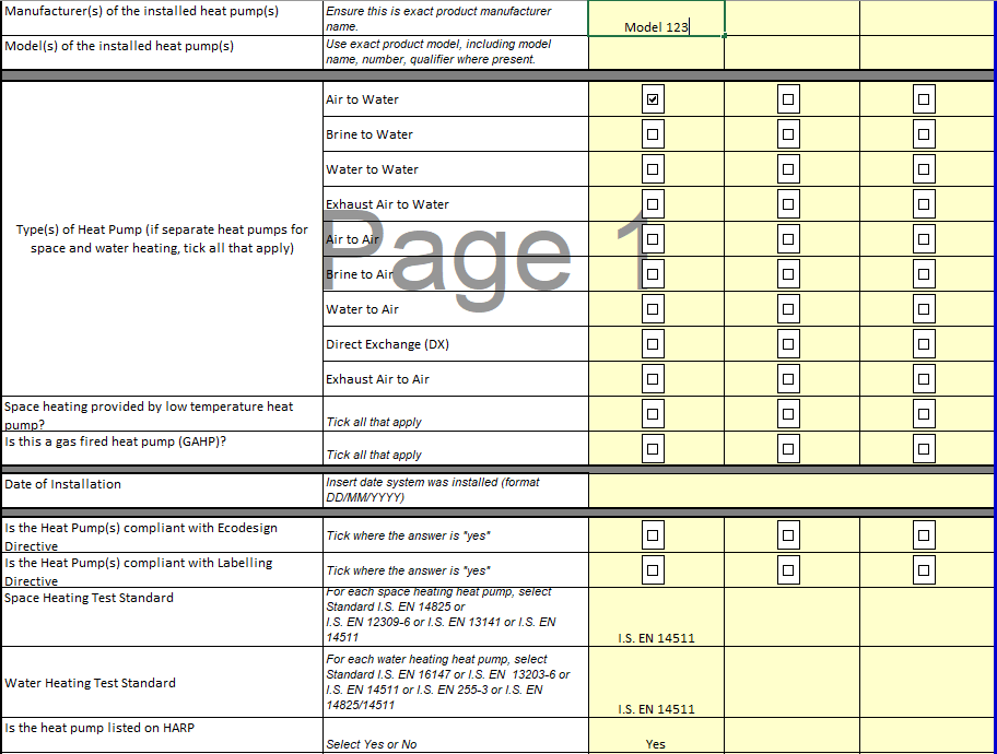
In this case the Assessor has received a copy of the designer/ installer sign off sheet from the installer confirming that the heat pump is not compliant with the Ecodesign / Energy Labelling directives and has been tested to EN 14511. The installer also confirmed that the heat pump is available on the HARP Database.

Design details
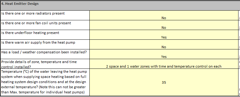
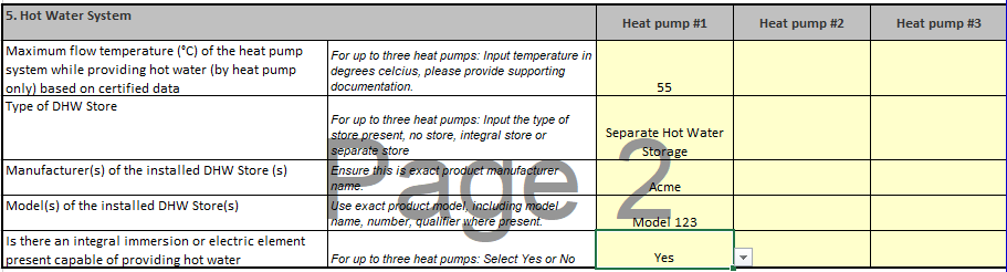
The installer also confirmed the following as part of the sign off sheet:
For existing dwellings, it may not always be possible to get a Designer/ Installer Sign off Sheet. In those circumstances, the Assessor should verify as much information as possible on site and follow the guidance set out in the DEAP Manual Appendix G and in this document.
¶ Source of test data
For heat pumps that are not compliant with the Ecodesign/ Energy Labelling Directive, the Seasonal Performance Factor (SPF) can be sourced using the approach used in DEAP previously:
- HARP Database
- Certified or CE marked data from accredited laboratory with test certificates to IS EN 14511-2, IS EN 255-2 or EN 15879.
- Use of DEAP Table 4a defaults for heat pump efficiencies.
In this case the heat pump is listed on the HARP database as confirmed by the designer/ installer:
¶ Entry in Heat Pump tool
Heat Pump Data
As with all heating systems in DEAP 4, information on the distribution system and controls is entered first in Space Heating > Controls and Responsiveness:
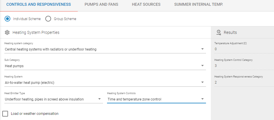
In order to add the heating system, we will first add it as a new library item as follows:
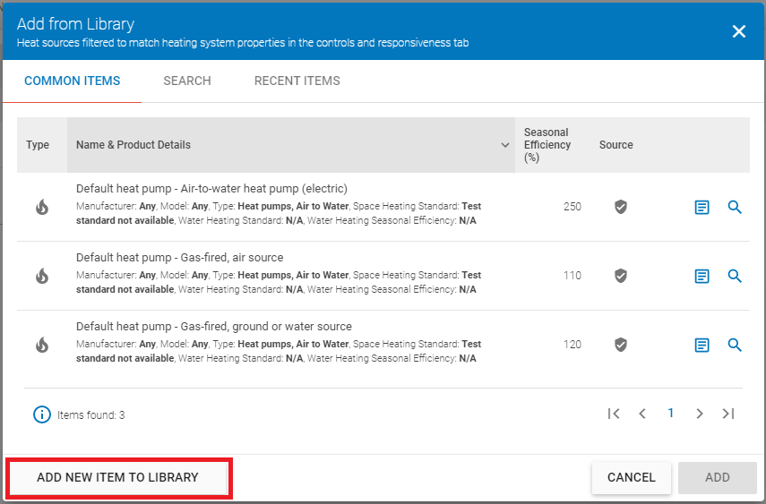
Click “Add New Item to Library” which brings you to the Create Library Item screen:
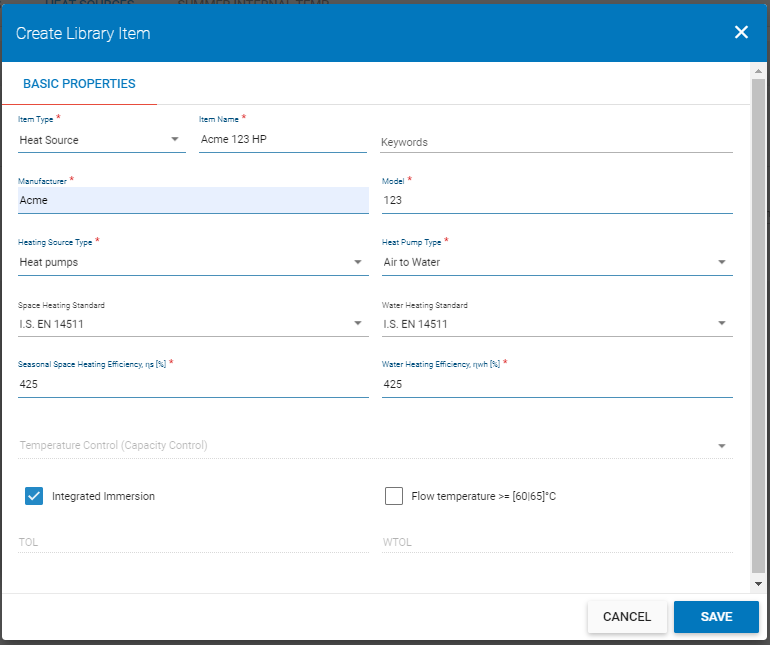
The details of the heat pump are entered as above, with an efficiency of 425% from the HARP listing. Note that “Integrated Immersion” has been selected, as specified in the Designer/Installer Sign-Off.
Also, a Flow Temperature >= [60/65]°C has not been selected because the Designer/Installer Sign-Off specified a maximum flow temperature of 55°C.
Click “Save” to add it to the library.
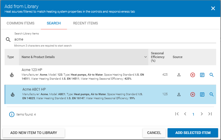
It has been saved to the Library; the next step is to add it to the assessment. Select “Add Heat Source” and use the Search tab to identify the system: in this case using the search term “Acme”.
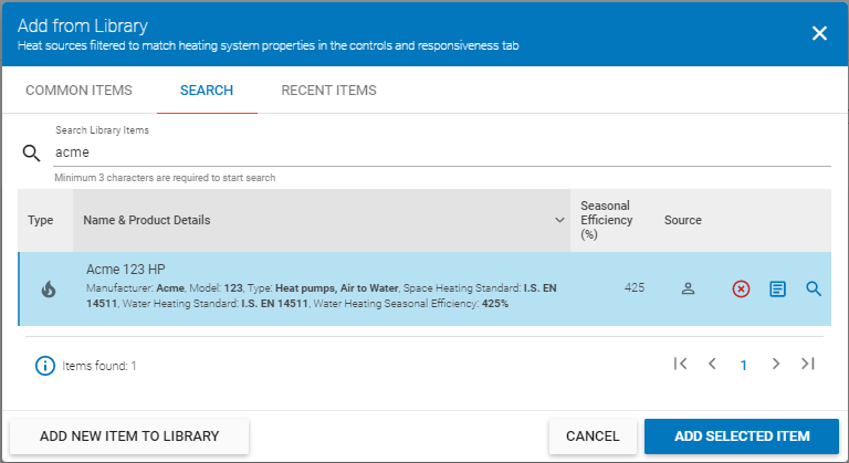
Select the item and click “Add Selected Item” to add it to the assessment. Information on the installation now needs to be added.
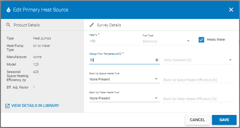
In this instance, “Heats Water” has been ticked because the heat pump heats both space and water. A flow temperature of 35°C has been entered, the default for underfloor heating as specified in the Designer/Installer Sign-Off.
Click “Save” to proceed.
One more piece of information needs to be entered: we have specified that the system heats water but DEAP needs to know more.
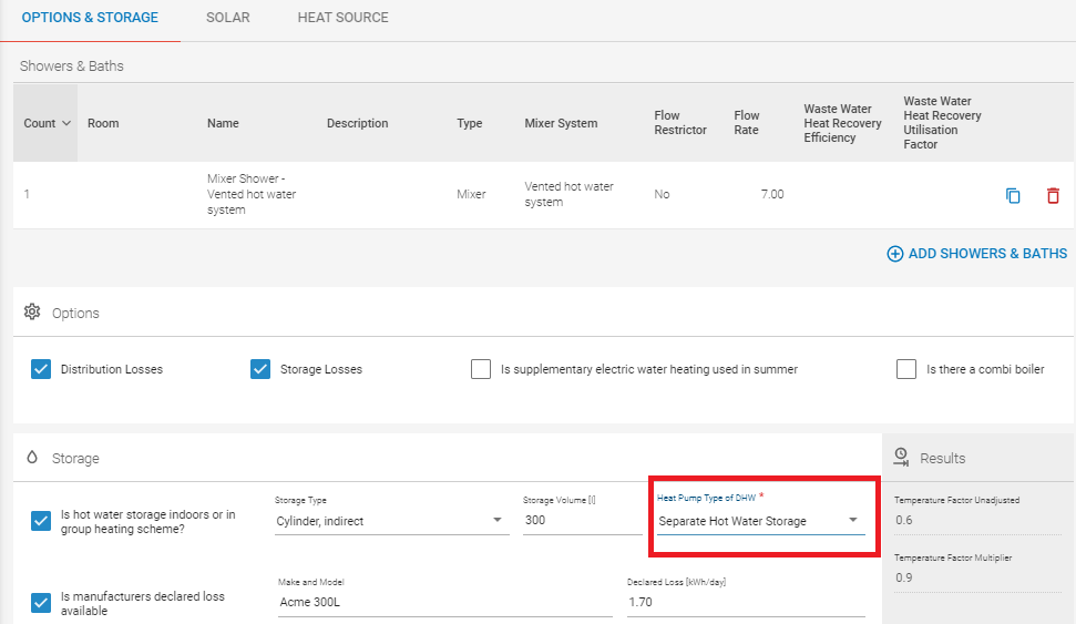
Go to the Water Heating > Options and Storage tab and select the appropriate value for “Heat Pump Type of DHW”, which in this case is ‘Separate hot Water Storage’ as specified in the Designer/Installer Sign-Off.
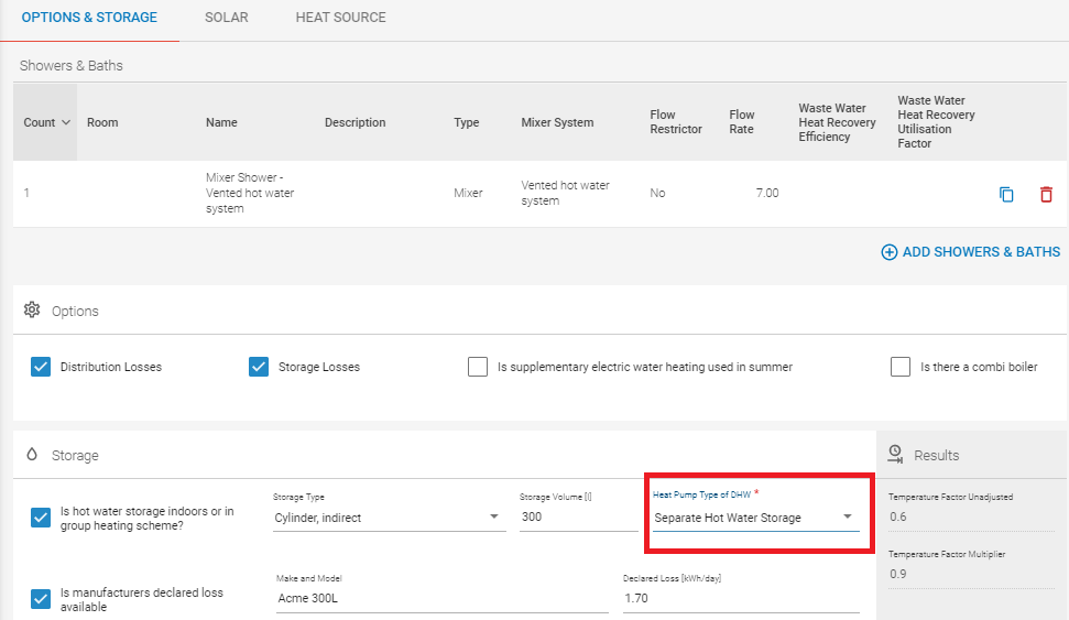
If you go to Water Heating > Heat Source you will see that the heat pump has been added as the main water heating system. Also, note that the efficiency has been adjusted to account for the integral immersion.


Example 2: Air-to-water heat pump compliant with Ecodesign/ Energy Labelling or EN16147 / EN14825

Heat pump parameters
The second example is based on the following:
Heat Pump installed in a dwelling after the 26th of September 2015 and compliant with the Ecodesign/ Energy Labelling Directives. It provides space and water heating.
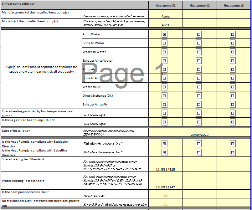
The Ecodesign directive requires that technical data is made publicly available declaring the test data for the heat pump to EN 14825 and EN 16147. The Assessor received the following details in the Designer/ Installer Sign off sheet.

¶ Design details
The designer/ installer also confirmed the following as part of the sign off sheet; this was verified by the Assessor on site.
Firstly the assessor noted that the designer/ installer had advised that the heat pump was designed to meet the full space heating and hot water demand (Section 3 of the Designer Installer Sign Off Sheet). The assessor confirmed this on site as no backup heaters were installed. Note: The Backup heaters identified in Section 3 of the Designer Installer Sign Off Sheet are heaters other than the heat pump itself, for example boilers. Backup water heaters which are part of the heat pump, i.e. integral immersions are identified in Section 5 of the Designer Installer Sign Off Sheet.
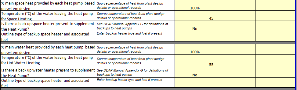
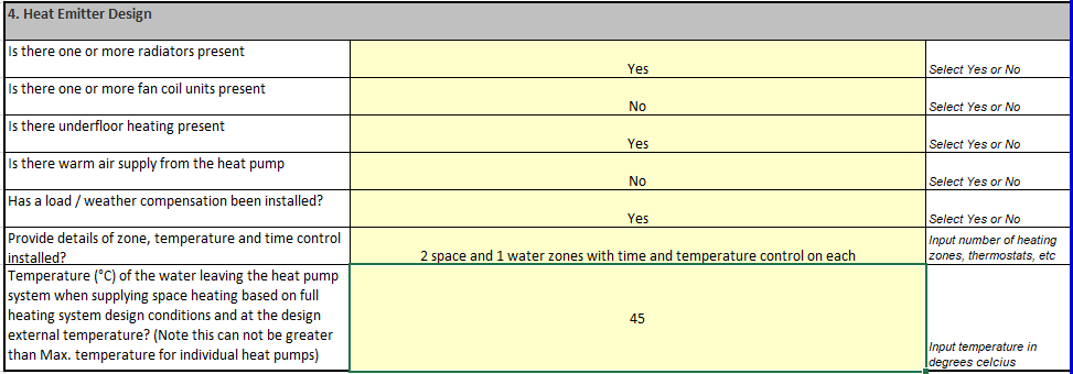
The dwelling is served by a combination of radiators and underfloor heating (taken from Section 4 of the Designer Installer Sign Off Sheet), with the design supply temperature being 45°C with the following controls.
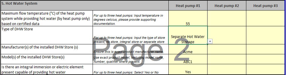
The heat pump was tested at a reference temperature of 55°C for water heating and had a separate hot water store (taken from Section 5 of the Designer Installer Sign Off Sheet).
¶ Source of test data
For heat pumps compliant with the Ecodesign directive, technical documentation outlining the declared test data must be made available to the public to comply with the directive.
Additional test data may be sourced that is in compliance with EN 14825 and EN 16147 from manufacturer’s literature referencing the relevant regulations/ directives, CE marked data or accredited test data as detailed in the heat pump guidance document. The following data is an excerpt from a publicly available technical data declaration in compliance with the Ecodesign directive referencing EN 14825 test data.
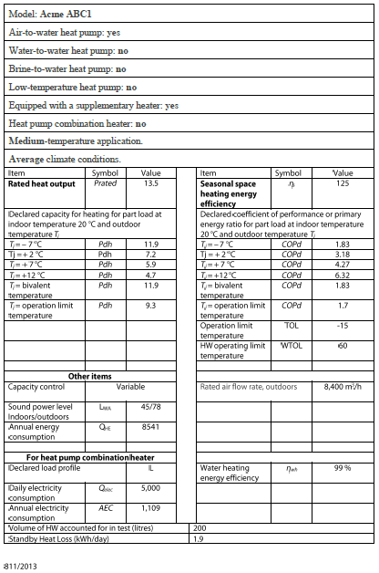
This data must be entered for the heat pump.
As in the previous example, to do this you must add the heat pump to the library.
In Space Heating > Controls and Responsiveness, enter the information on the heating distribution system and heating controls, as in Example 1. Then in Space Heating > Heat Sources, click “Add Heat Source” and then “Add New Item to Library”.
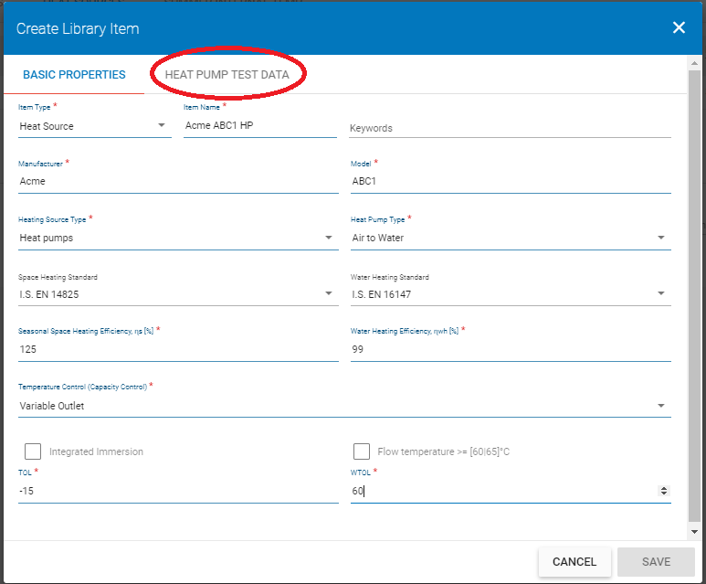
This page contains some of the data from the Ecodesign data sheet.
Note the second tab called “Heat Pump Test Data” – circled in red – which is where the rest of the Ecodesign data will be entered.
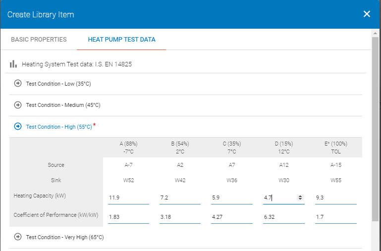
In the screenshot above we can see the space heating data (EN 14825) from the Ecodesign data sheet has been entered. Note that data must be entered for Test Condition - High (55°C).
Data from the other test conditions must be used if available but the High Temperature (55°C) is the only one that is required. In this case, only the High Temperature data has been provided so that is all that is entered into DEAP 4.
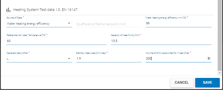
The water heating data (EN 16147) is entered in the lower half of the page.
Click “Save” to add this item to the library and then add it to the assessment. As in the previous example, data specific to the installation must now be entered:
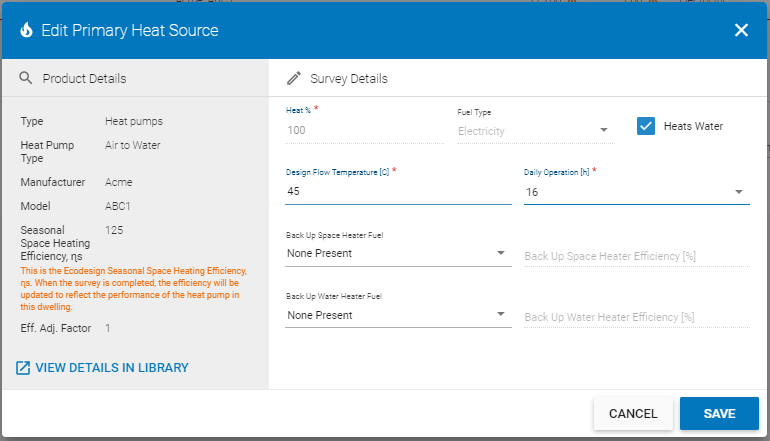
Click “Save” to add this item to the assessment and then make the necessary changes in Water Heating, as shown in Example 1.
Note: As only one set of test data is available (at 55°C) the tool bases the Efficiency on a flow temperature of 55°C irrespective of the actual flow temperature. Where more than one set of data is available, the tool will then adjust the efficiency based on the flow temperature using interpolation between the two sets of test points. All sets of available valid test data must be used.
The run hours can also impact on the results. For example if the heat pump was installed to operate 8 hours a day to meet internal environmental conditions - i.e. a timer on the heat pump only allows the heat pump to operate 3 hours in the morning and 5 hours in the evening – then the ability of the heat pump to meet demand will be reduced. In this instance that leads to a relatively poor space heating efficiency:


Example 3: Air-to-air heat pump compliant with Ecodesign/ Energy Labelling Directive or EN16147 / EN14825

Heat pump parameters
The calculator caters for a number of heat pump types heating air rather than water: Air to Air, Brine to Air and Water to Air.
This example looks at how an Air to Air heat pump would be entered into the calculator and DEAP. Taking the details from Example 2, the air to water heat pump is replaced with an air to air heat pump. A similar methodology would be used for Brine to Air or Water to Air.
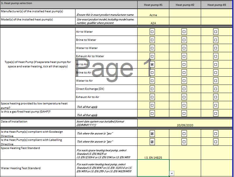
As an air to air heat pump, it is providing space heating only. The designer/ installer sign off sheet has been updated as follows:
¶ Design details
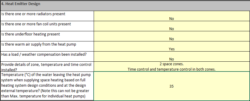
The designer/ installer also confirmed the following as part of the sign off sheet; this was verified by the Assessor on site. Firstly that the heat pump was designed to meet the full space heating demand with no backup heaters installed (as per Section 3 of the Designer Installer Sign off sheet). Water heating is supplied by an alternate system rather than heat pump.
The dwelling is served by warm air supply; therefore the default supply temperature is 35°C:
¶ Source of test data
Similar to Example 2, for heat pumps compliant with the Ecodesign directive, technical documentation outlining the test data declaration must be made available to the public to comply with the directive. Assessors can also source data from manufacturer publications referencing the relevant directives/ standards.
¶ Data Entry
As in previous examples, you will first need to enter information on the distribution system and controls in Controls and Responsiveness,
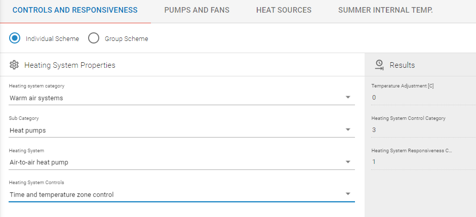
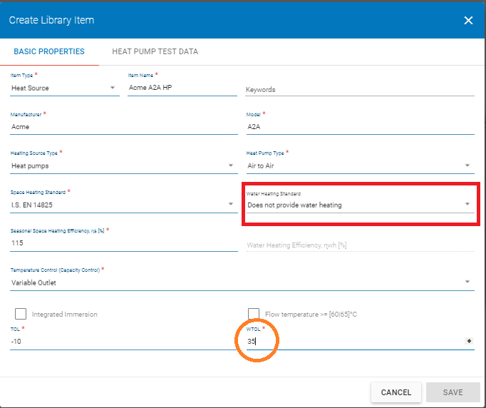
and then add the heat pump to the DEAP 4 library:
Note that in the Basic Properties page for the heat pump we have specified that the heat pump does not provide water heating (highlighted in red). Also note that a default WTOL of 35°C is used for air-to-air heat pumps (circled in orange).
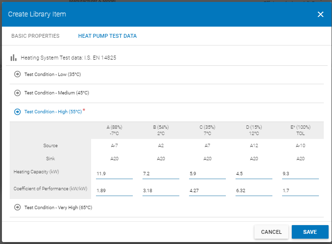
In the Heat Pump Test Data page, the test data associated with EN 14825 is taken directly from the publicly available technical data declaration in compliance with the Ecodesign directive or directly from manufacturer literature referencing directives/ regulations or accredited/CE marked test data (as shown in Example 2).
For “to Air” heat pumps there is only one set of test conditions under EN 14825, namely the High Temperature – 55°C data, therefore no data is entered for Low, Medium and Very High Temperature test conditions.
Using a Design Flow Temperature = 35°C and Operating Hours = 16 hours, gives the efficiency as seen below:

Increasing the operating hours to 24 hours, would increase the efficiency of the system.

Example 4: Exhaust Air-to-water heat pump compliant with Ecodesign/ Energy Labelling Directive or EN16147 / EN14825
The Exhaust Air to Water Heat Pump is similar to other “to Water” heat pumps, so the methodology is as per Example 2 with the following changes.
One key additional piece of information is required.
In Ventilation, the Ventilation Method is set to “Exhaust Air Heat Pump” and the specific fan power and flow rate of the system are entered, as shown below.
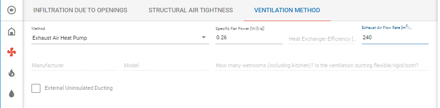
The air flow rate should be taken from the Ecodesign Technical Data Sheet for the heat pump. Further details are given in Section 2.6 of the DEAP Manual.

Example 5: Air-to-water heat pump compliant with Ecodesign/ Energy Labelling Directive or EN16147 / EN14825 with backup heater.

Design Details
This example is based on Example 2 but with the addition of a backup heating system for space heating and water heating.
As per the Heat Pump Methodology guidance in DEAP Manual Appendix G, any system that is acting as a backup to the heat pump is considered part of the Main Heating system and is therefore not considered a secondary heater.
The backup must heat multiple rooms - like the heat pump - rather than be a single room heater (such as a typical secondary heater in DEAP).
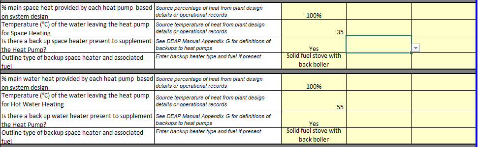
In this case, the designer/ installer has confirmed that a backup heater is present in Section 3 of the Designer Installer Sign Off Sheet: a solid fuel stove with back boiler supplying space and water heating.
The heat pump is already in the library so we can search for it and select it,
Then we need to enter the details specific to the installation; in this case that means specifying the backup heating for space heating and water heating:
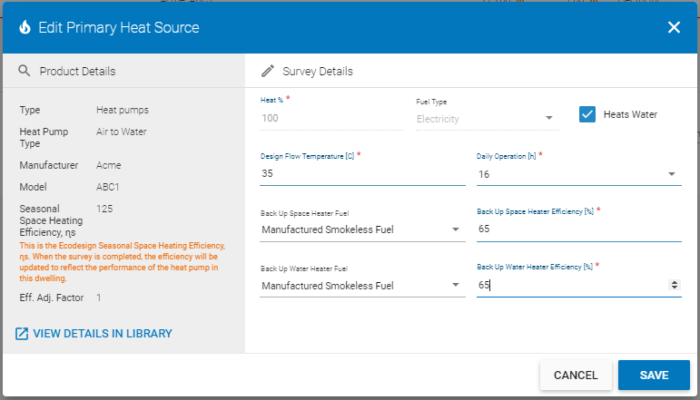
In this case there is no information provided for the stove with back boiler so the default efficiency from Table 4a is used.
Note that when the system has been added there are warning messages.

In particular, if you hover over the red triangle on the left-hand side, you are advised as follows:
“Please provide Type of DHW within the Water Heating Options and Storage section”.
So, you need to go to ‘Water Heating > Options and Storage’ to select the ‘Heat Pump - Type of DHW’ as in the screenshot below where “Separate Hot Water Storage” has been chosen.