¶ Wind turbines

Wind energy
The wind turbine calculation is carried out in the 'OnSiteGen' tab. DEAP supports up to three wind turbines. Where the total annual output of a turbine has been determined from a calibrated anemometer located at the turbine position, this figure may be entered directly. Otherwise, DEAP calculates annual generation from the following inputs for each turbine:
- Rotor diameter in metres;
- Hub height in metres;
- Terrain type: Rural, Low rise urban/suburban, or Dense urban.
The swept area of the rotor is calculated as 0.25 × π × (rotor diameter)². A wind speed correction factor, dependent on hub height and terrain type, is applied to the annual average wind speed, which is taken from Dublin Airport 1991–2020 meteorological averages (Met Éireann). This gives a corrected wind speed representative of the turbine location. Annual electricity generation is then calculated from the swept area, the corrected wind speed, and a combined aerodynamic and electrical efficiency parameter of 0.24, which represents the product of the aerodynamic power coefficient, generator efficiency, and inverter efficiency. Where turbines differ in hub height or rotor diameter, the calculation is applied to each turbine separately and results are summed.
Annual generation is distributed across months in proportion to monthly wind energy factors derived from mean monthly wind speeds at the Dublin Airport reference station. This accounts for the seasonal variation in wind resource, which is significant in the Irish climate. The monthly self-use and export split follows the same approach as for PV, comparing monthly wind generation against total electricity demand. Where both PV and wind generation are present, combined self-use is subject to the same correction to avoid exceeding total monthly demand.
The primary energy factors and CO₂ emissions factors applied to both self-use and exported electricity are shown here.
Guidance on re-use of data for Wind Turbines can be found here

M2.1 Horizontal-axis wind turbines
Where the total annual output of a turbine has been determined from a calibrated anemometer located at the turbine position, this figure may be entered directly.
Otherwise, annual electricity generation is calculated as follows:
The swept area of the rotor is:
A = π × (d/2)² (M10)
where d is the rotor diameter in metres.
The annual average wind speed at the site is taken from Dublin Airport 1991–2020 meteorological averages (Met Éireann). A wind speed correction factor, dependent on hub height and terrain type, is applied to this reference speed to obtain a corrected wind speed s at the turbine location, using Table M2. Intermediate hub heights are interpolated linearly between the values in Table M2. The terrain types are Rural, Low rise urban/suburban, and Dense urban.
The output power of one turbine at the corrected wind speed is:
Pwind = CP × G × IE × A × 0.6125 × s³ (M11)
where CP is the aerodynamic power coefficient, G is the generator efficiency, IE is the inverter efficiency, and 0.6125 × s³ is the power density of the wind in W/m². The product CP × G × IE is taken as 0.24 for horizontal-axis turbines.
Annual electricity generation is then:
Ewind = Pwind × 1.9 × 8766 × 0.001 (M12)
where 1.9 represents the wind speed variation function, 8766 is the average number of hours per year, and 0.001 converts from Wh to kWh.
Where turbines differ in hub height or rotor diameter, equations (M10) to (M12) are applied to each turbine separately and results are summed.
¶ M2.2 Monthly distribution
Annual wind generation is distributed across months in proportion to monthly wind energy factors derived from mean monthly wind speeds at the Dublin Airport reference station. The wind energy factor for each month is:
Fm = sm³ × nm (M13)
where sm is the mean monthly wind speed (m/s) and nm is the number of days in the month. Monthly generation from each turbine is then:
Ewind,m = Ewind × Fm / ΣFm (M14)
¶ M2.3 Self-use and export
The monthly self-use proportion for wind generation is:
β = min(Dm / Ewind,m, 0.7) (M15)
where Dm is the total monthly electricity demand as defined in M1.2. The cap of 0.7 reflects the practical limit on coincidence of wind generation and demand. Monthly self-use and export are then calculated from β using equations (M8) and (M9).
¶ Vertical-axis wind turbines
The procedure outlined above for horizontal-axis may be used for vertical-axis wind turbines, with the following adjustments:
1. The area swept by the blade is calculated as follows:
Table 8.3 - Area calculation for different types of vertical axis turbine
| Blade type | Swept area |
|---|---|
| Savonius | Height x diameter |
| Darrieus (egg-beater) | 0.65 x (height x diameter) |
| H-Darrieus | Height x diameter |
| Helix | Height x diameter |
| Others | If the area swept by the blade is rectangular, Height x diameter; If the area is not rectangular, please consult the helpdesk. |
2. The product of CP, G, and IE to be used in the formula for the power output Pwind is 0.10.
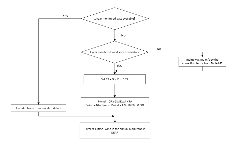
Table 8.4 - Wind Speed Correction Factors
| Terrain type | Height of turbine hub above tallest nearby objects (m) * | Correction factor |
|---|---|---|
| Dense urban (city centres with mostly closely spaced buildings of four storeys or higher) | 10 | 0.56 |
| 5 | 0.51 | |
| 2 | 0.40 | |
| 0 | 0.28 | |
| Low rise urban/suburban (town or village situations with other buildings well-spaced) | 6 | 0.67 |
| 4 | 0.61 | |
| 2 | 0.53 | |
| 0 | 0.39 | |
| Rural (open country with occasional houses and trees) | 12 | 1.00 |
| 7 | 0.94 | |
| 2 | 0.86 | |
| 0 | 0.82 |
Use linear interpolation for intermediate values. For hub height higher than the maximum given for the terrain type use the highest for that terrain type (i.e., 0.56, 0.67 or 1.00).
* including objects such as mature trees, landmass, building (either neighbouring buildings or actual dwelling being assessed) within a radius of10 times the turbine hub height.